Document your work and explain what are the limits of your printer(s) (in a group or individually)
Individual assigment:
Design and 3D print an object (small, few cm3, limited by printer time) that could not be easily made subtractively
3D scan an object, try to prepare it for printing (and optionally print it)
Learning outcomes:
Identify the advantages and limitations of 3D printing
Apply design methods and production processes to show your understanding of 3D printing.
Demonstrate how scanning technology can be used to digitize object(s)
Summary of the week
This week was pretty interesting, although it was disturbed by Finnish winter break (holiday week). Especially I enjoyed of 3D scanning, but 3D printing was also pretty interesting exercise.
I didn't have previous hands-on experience of using 3D printers or 3D scanning applications/hardware, alhtough I have seen printers and scanners in the action in different educational technology exhibitions and workshops
It was very useful to test design rules for different 3D printers and see how different cabapilities those printers had. I did learn that I need to use different materials, adopt different algorithms, and have different strategies in dealing with complex structures depending the printer. Thus, it is necessary to acquire this knowledge in order to choose the most appropriate 3D printers for different activities.
Part A. 3D Design and printing
I did use Autodesk Fusion for designing my 3D artefact. Reason for that is the fact, that it's both powerful design program, but also one that I have learnt to use in addition to Tinkercad :)
Anyway, I browsed many many excercises done by FabLab Oulu FabAcademy alumnis 2018-2019. I found that 3D box might me doable in the limited timeframe and beginner's skills that I have
Box was also as an example project done by Michael Oduor in FabAcademy 2019. It was highlighted as an example in our local 3D printing & scanning wiki by our instructior Behnaz. So I did choose it to be my approach
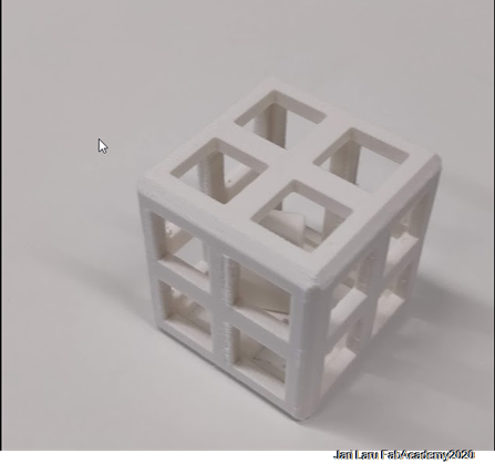
I did study earlier implementations of the cube inside of the cube and then did sketch (on my head) that sides of the cube should be different than in e.g. Oduor's example. I chose to add four squares to each side of the cube. (see end result below)
In this task the aim was to design artefact, which can be manufactured only additively, meaning an object that could not be milled or laser cut. For this, I chose to design a cube inside another cube. Additive manufacturing is designing by layering components whereas subtractive is when layers are cut from a design until the desired model. The design outlined below is only possible to fabricate using additive manufacturing because the inner cube’s dimensions are slightly bigger than the holes on the sides of the bigger cube, the two cubes are not attached, the smaller cube moves freely inside the bigger one and it can’t come out through the holes.
My workflow for designing 3D cude with smaller cube inside of that
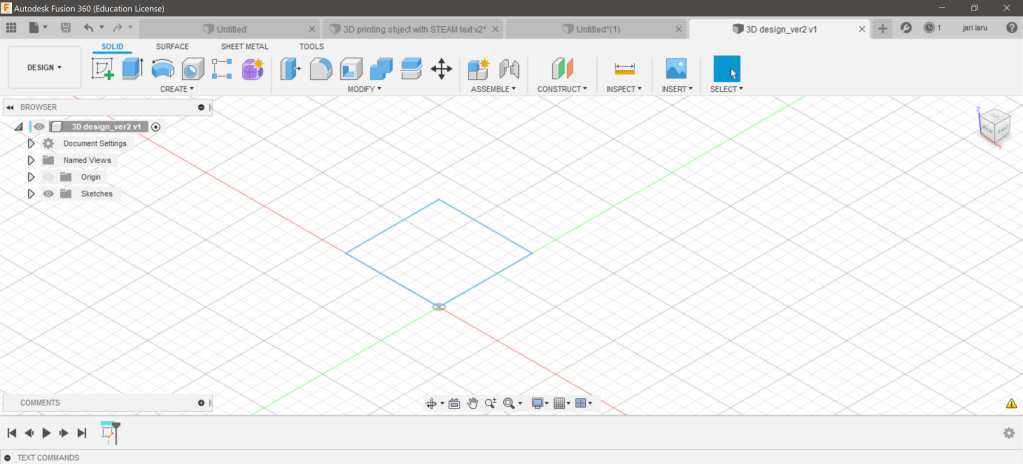
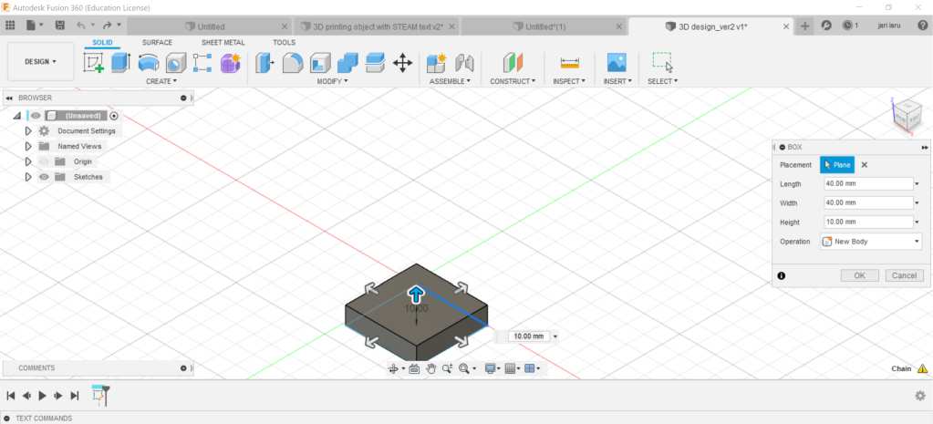
Step 1. Sketch a box
Choose: "create / box" from Create menu
Then give measures for lenght and width of box. In my case i did use 40mm for both
Next add height of the box by using same measure than you did use with lenght and width. So, in my case 40mm
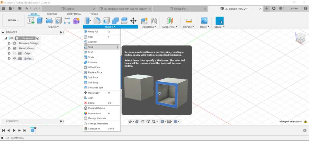
Step 2. Make your box empty (hollow)
Choose: "hollow" from "modify" tab
Choose whole object (all faces of the box) that inside of the object will be made hollow, but faces remain closed
Add inside thickness of the hollow box. I did use 3mm
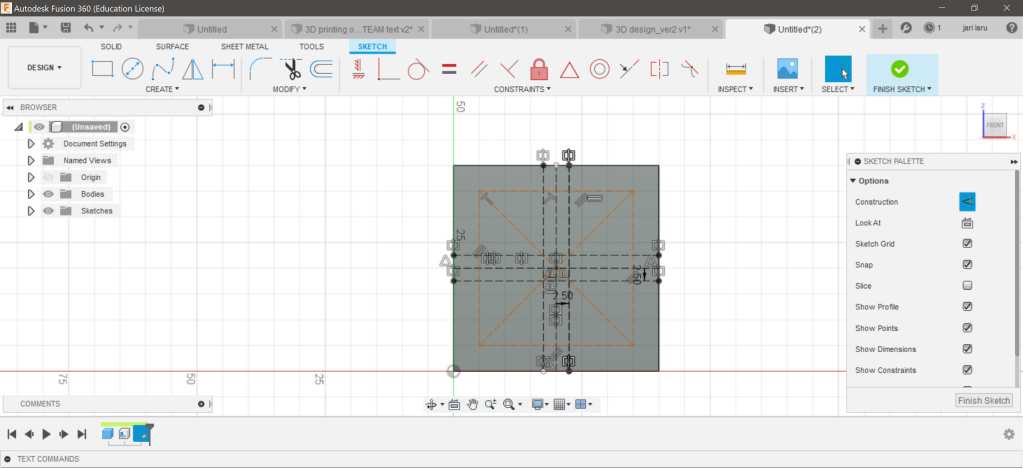
Step 3. Sketch squares into side faces of the cube
Draw horizontal and vertical construction lines (in construction mode) in middle of three faces of the cube
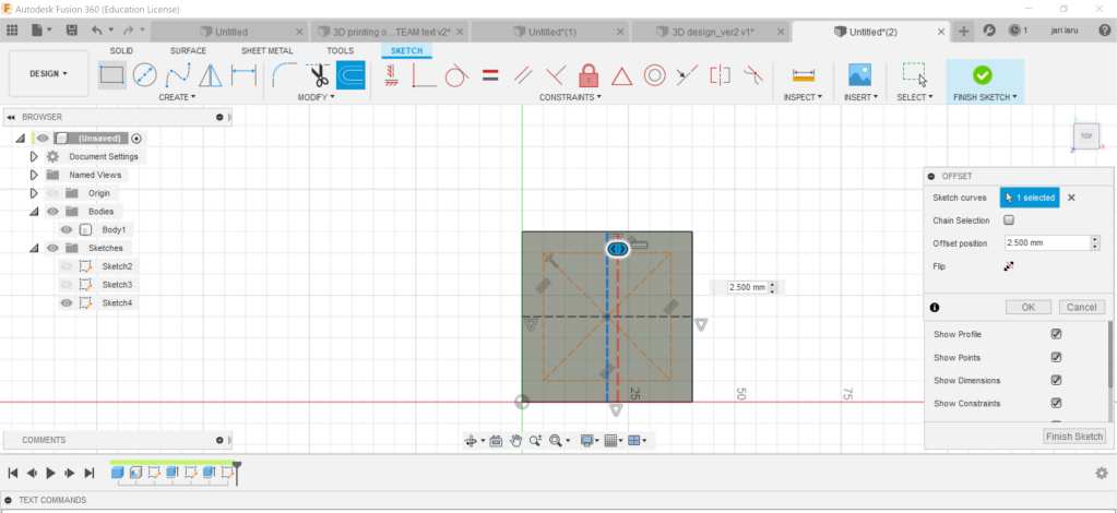
Choose one of the construction lines and:
Use "offset" function to add new construction line next to it. I used 2.55mm as a value in offset
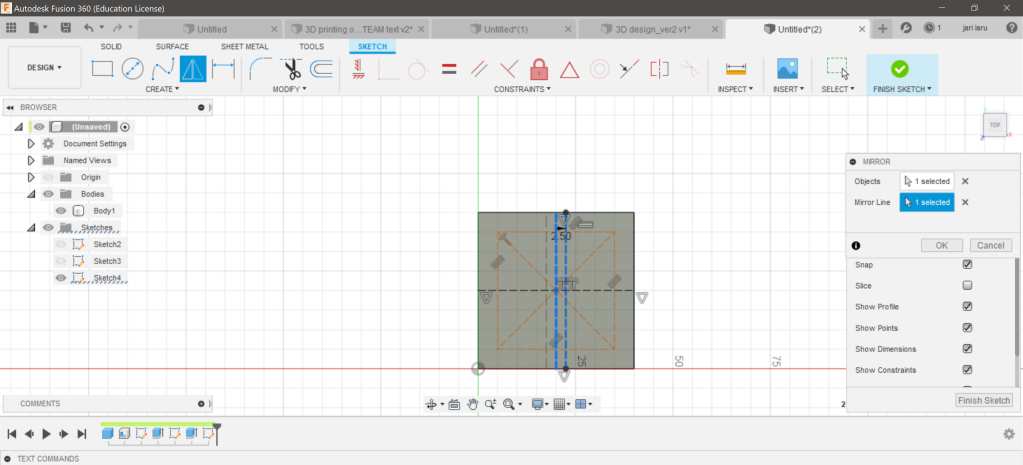
Mirror new construction line by using "mirror" tool. After that you should have three construction lines parallel
Do the same to to all of your construction lines created in first phase
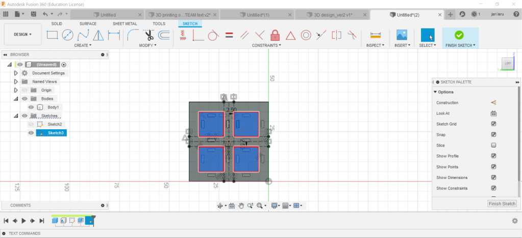
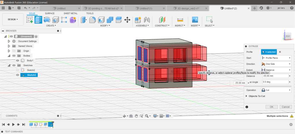
Step 4. Sketch four rectangles to each faces of the cube and extrude them
In this phase you can use scaffolds (construction lines) to sketch rectangles in symmetry to each sides of the cube. I know that I had been able also to use more advanced approach, but this is the level of my skills now :)
If you are not in sketch mode, click sketch and choose plane
Pick up "2-point rectangle" from sketch menu
Draw four rectangles in symmetry to each 3-sides of the cube by using construction lines as scaffold
End sketch mode and pick up "extrude tool" from the menu
Choose four rectangles from one side of the cube
Use extrude so that it goes also through of the opposite face. Repeat this and previous phase to each side of the cube where you have sketched four rectangles
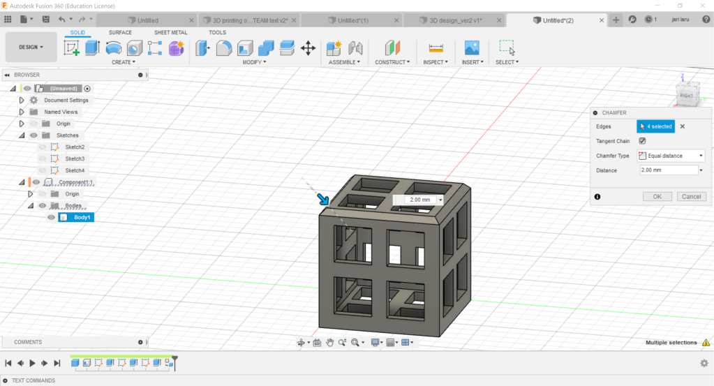
Step 5. You can decorate your design by using chamfer function
Go to "modify" -menu
Choose "chamfer" -tool
Choose edges that you wan't modify
Spesify distance in the tool (strenght of chamfer effect)
repeat this to as many edges as you want (to get style that you want to achieve)
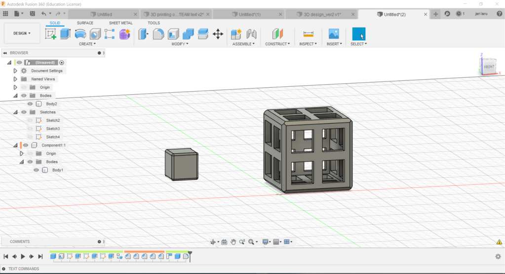
Step 6. Design smaller object to be put inside of the box
Sketch 2-point square and extrude it by following guidelines described in the step 1.
Be careful that you set dimesions for the smaller cube bigger than dimensions of the height and with of the holes in the bigger cube.
If you like, you can do similar chamfer operations to small cube, than you did to larger cube (see step 5)
When small cube is ready, move it inside of bigger cube.
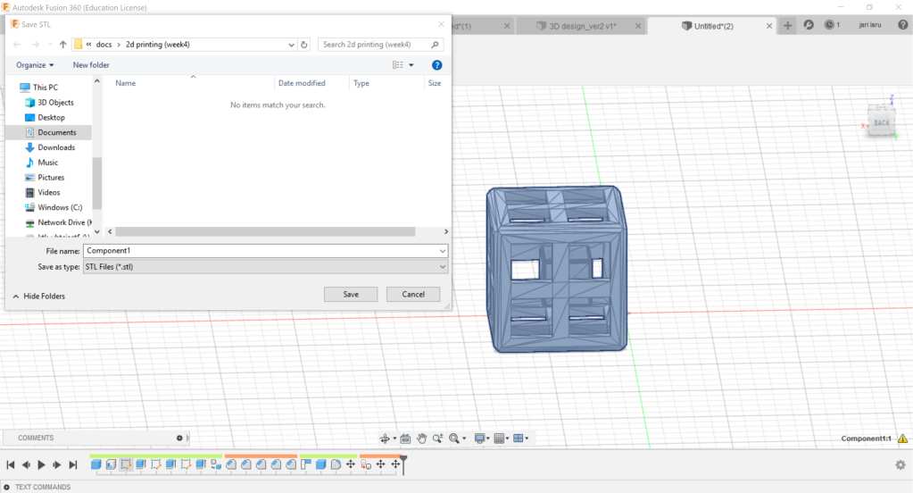
Step 7. Export your design into .stl-format
When your design is ready, it needs to be exported to be 3D-printed.
Go to file menu (top-left corner in Fusion360)
Choose export
Select file format: .stl and export document!
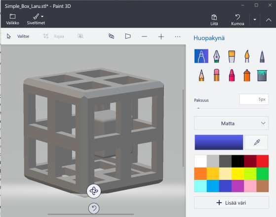
Preview your .stl file by using some default viewer (in the picture below: Paint3D in Windows 10)
Printing my design with Stratasys 3D printer
Preparing .stl file for printing
Before printing designed artefact with Stratasys Fortus 380mc printer, file needs to be prepared for that.
GrabCAD software will be used for that purpose. It's 3D printing software for Stratasys 3D printers.
Workflow for preparing the file:
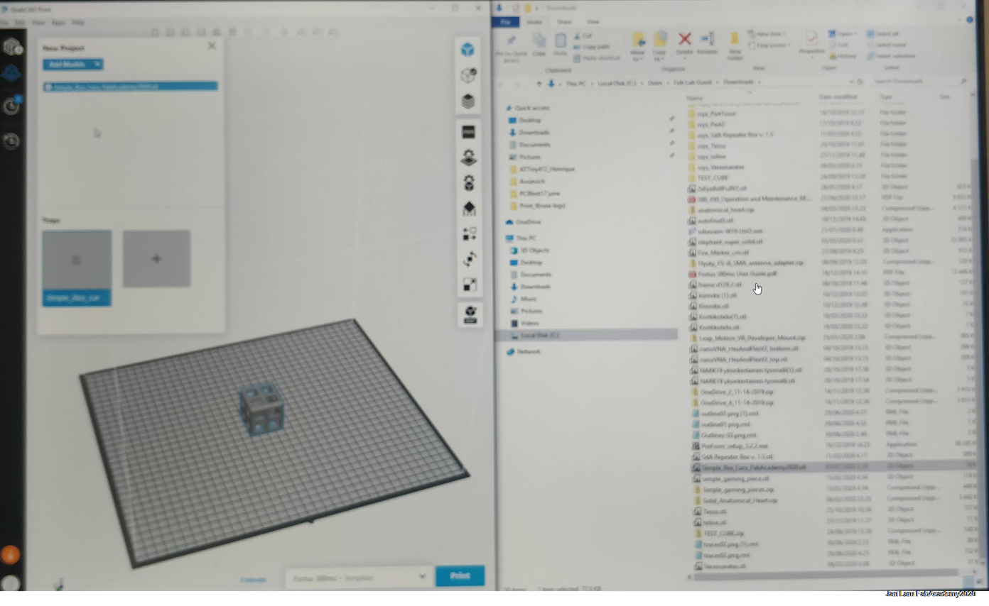
Open .stl-file into software: file > new project > add models
Drag model into print area (see first figure below)
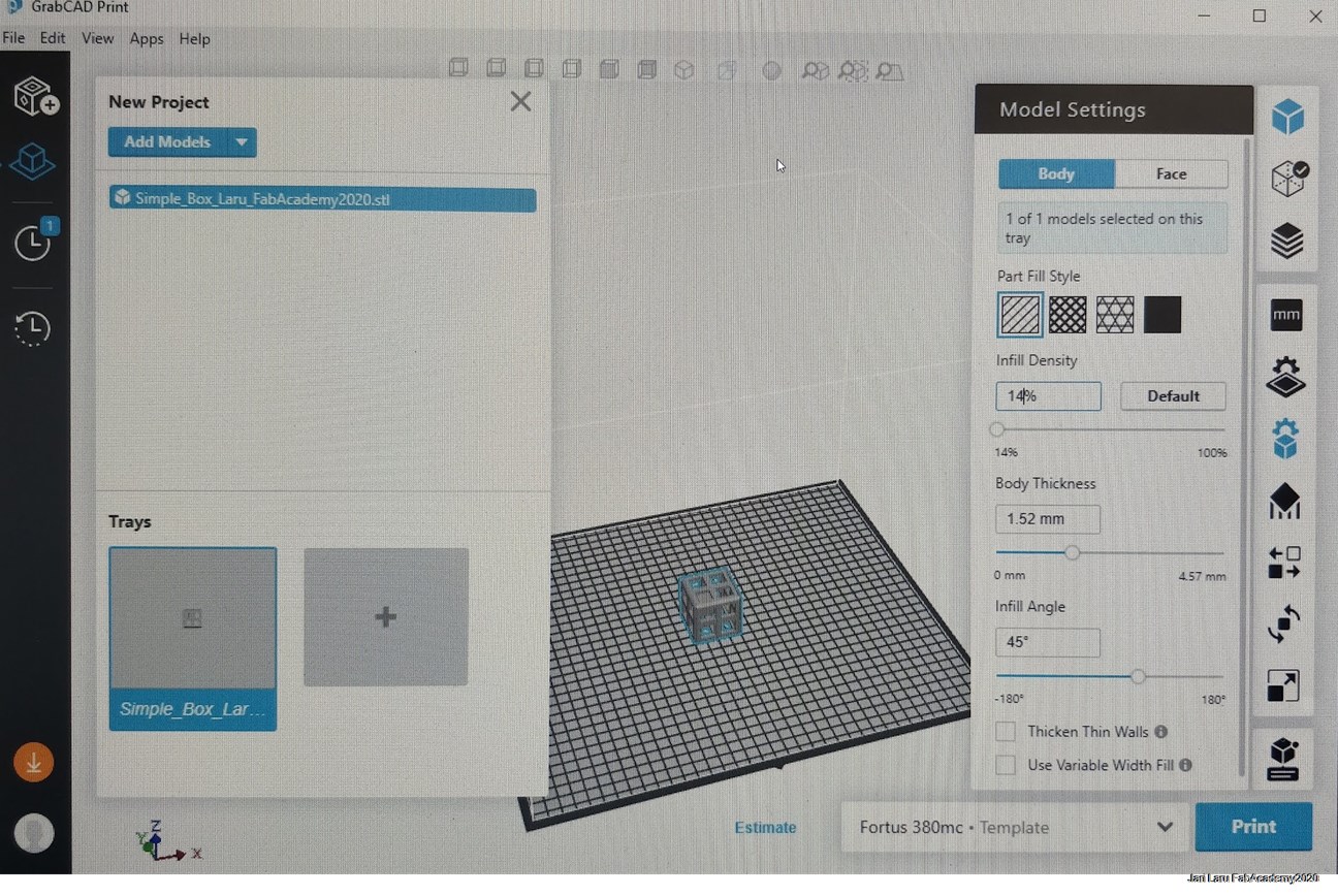
Change model settings (floating menu on right) so that
Infill percentage of print: I did set it to 14%
Scale of the object: my object is already small enough, so no need for that
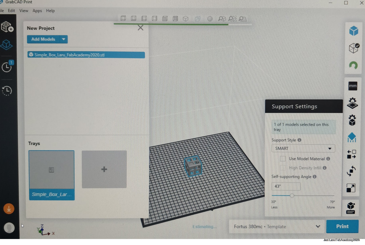
Support settings: SMART option is recommended. Software calculates places where support material is needed.
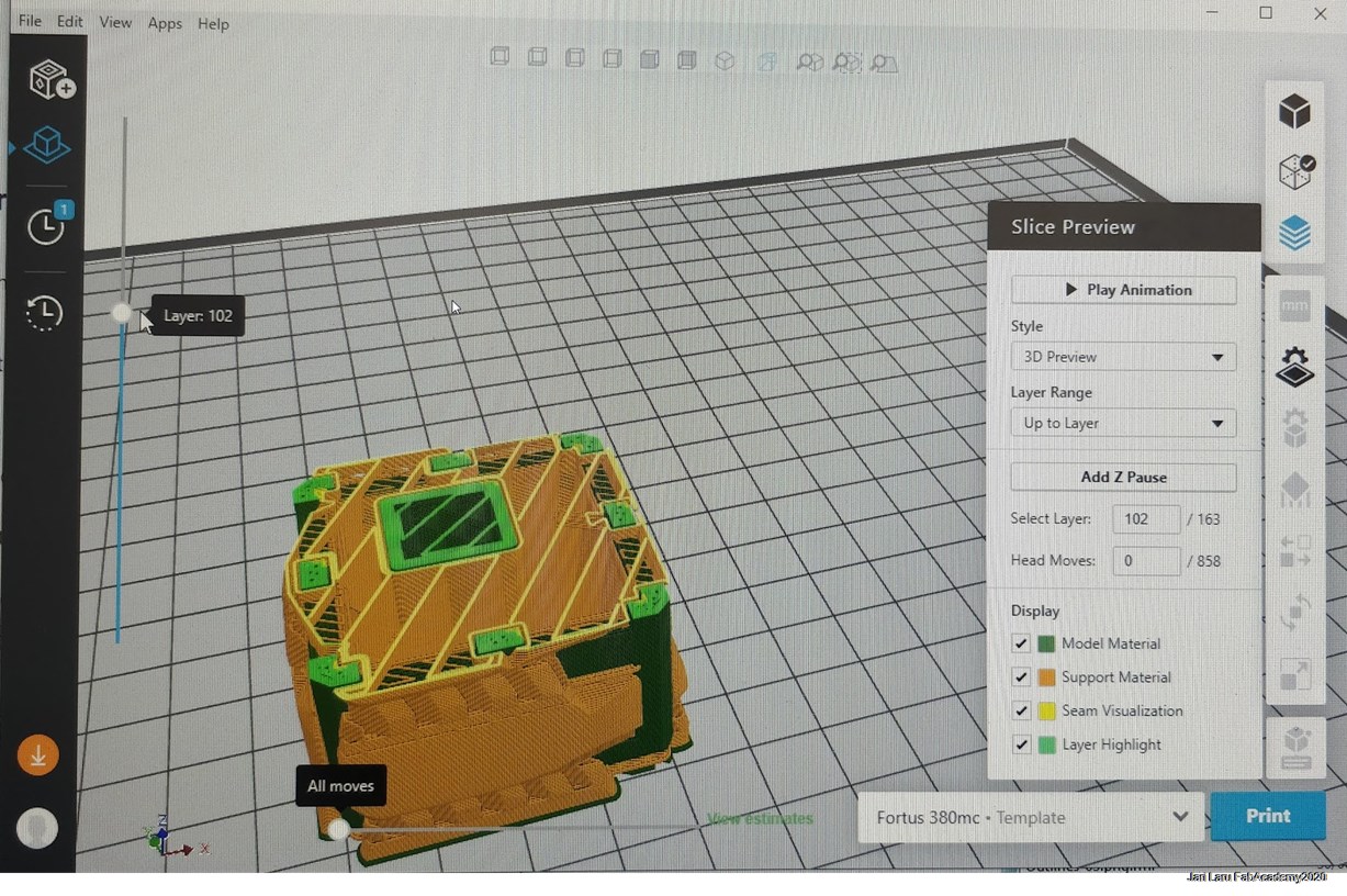
Slice preview: This option will show as an animation how printer will print the artefact
Export file as CMB format: file > export > cmb
Sending the file to StrataSys 3D-printer
Next CMB file will be sent to StrataSys printer. This can be done by using Control Center of the StrataSys printer.
Workflow for that:
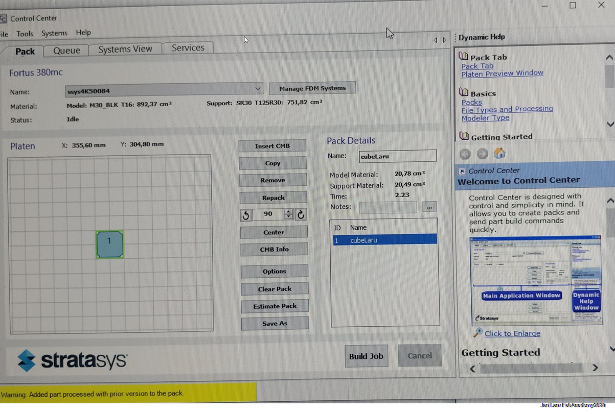
Drag and drop exported CMB file from the file explorer to control center
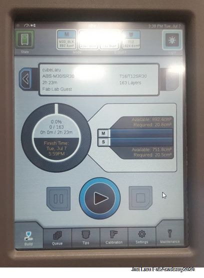
Control Center will show dimensions of the artefact and tell how long it might take to print it.
Click build job to send CMB file to StrataSys printer
Operations needed to done for StrataSys printer before printing
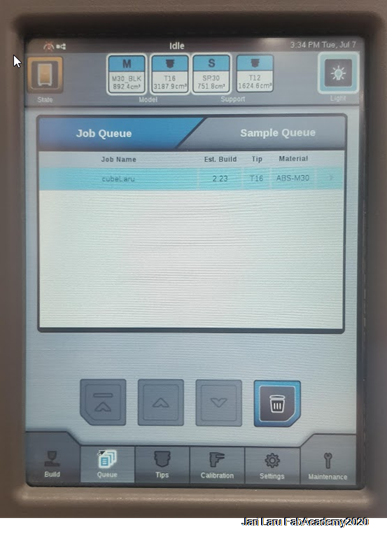
Now you have got your CMB file into 3D-printer. You can see in the Queue section in the touchscreen display of the Stratasys. Quite often there are a lot of designs waiting to printed, so if you are in hurry, you can change the order of the artefacts by using arrow keys.
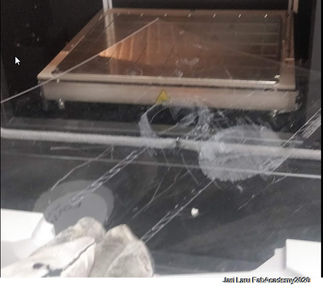
Next you will need to add build sheet into printing cabinet. If sheet is not put correctly into printer, display will show warning: "insert the build sheet". Sheet needs to aligned with the pins on the corners of the printer and fixed by the vacuum inside the printing cabinet.
When sheet is correctly placed, display will show info: "Ready to build #3D".
Now you can spesify where your design will be printed. Choose correct place and press ok. Then click "build" to see details of the design and time estimate for printing job.
Click "play" to start printing
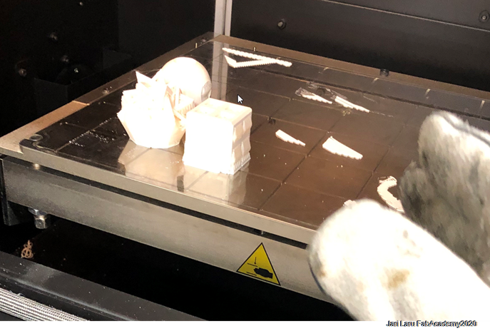
Printed object needs to be finalized by using special treatment
After the printing build sheet was removed from the the printer. CAUTION: When you print your own artefact, please wear gloves, because the Stratasys printer is HOT.
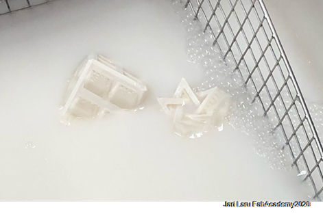
First printed artefact was just pulled off from the build sheet and some of the leftovers were removed. However, most of the support material need sodium hydroxide bath, which is the main step after printing.
Artefact printed with Stratasys printer needs normally overnight treatment in that liquid, but if the desin is bigger, then time requirement can be also higher
After one day, my design was removed from the sodium hydroxide and washed. Final result seems to equal to original design presented above in this documentation.
Part B. 3D Scanning
I was pretty interested in to test 3D scan application available for smartphones. Reason for this is the fact that I am responsible for technology enhanced learning in the faculty of education here at the university of Oulu
I have seen how our students love to use their own mobile phones and laptops for their tasks. It would be quite nice, if I can introduce also a possibility to use their devices with that kind of futuristic use case.
Mobile phones are example of the ubiquitous and pervasive techology, so also from that perspective it's interesting to test how mobile phones could be used as a tool for 3D scanning. Recently tablets and phones have started to get special features which do support 3D scanning. For example, iPad pro has got integrated 3D scanner and similar technology will be available also in the mobile phones.
EDIT: FabLab Oulu got new interesting computer with 3D scanning capabilities in May. HP Sprout has integrated turntable and camera for 3D scanning purposes. Unfortunately COVID-19 prevented me of testing that device. However, it was partly familiar already, because I have seen it in many technology workshops and exhibitions earlier.
Next year I will also start few new courses based on new curriculum of the Faculty of Education. I am responsible for courses such "technology enhanced learning and digital fabrication" and "emergent technologies for learning". This kind of technological enabler is interesting add-on to my course lessons.
Does my mobile phone (android) support ARcore? and Why it's important?
Before doing "anything" I wanted to test that my phone does support Augmented Reality Core (integrated into Android, but device needs to support it). For iPhone owners similar functionalities are branded under the term "ARkit"
Yes! ARcore is important, because with that you can use augmented reality functions for putting your scanned 3D object onto any surface around you. I think that now from the perspective of K-12 school students (I am teacher educator). They would be motivated also to learn some principles of augmented reality in the context of 3D scanning, i suppose.
On the other hand, it is also one of the requirements for holotuber application (volumetric holographic video capture) that I did try also in this scanning task. ARcore is used to project "hologram" of the streamed speaker onto surface (e.g. to table). Unfortunately one of the Holotuber components didn't work properly and I didn't succeed with that approach. I will contact developer and continue later on with that (see separate section for more accurate elaborations)
I did test ARCore support in the practice, by installing IKEA place application to my phone. Boom, pretty soon my kitchen was full of diferent IKEA products, so, it did work :)
Mobile 3D scanning tools that I did choose to test on my device (android Oneplus 5T)
Scann3D
Qlone - 3D Scanning and AR solution
First application: Scann3D
User interface of Scann3D looks good, so I thought that this might be GOOD 3D scanner. However, i was pretty wrong. Anyway, let's start with Andrdoid appstore overview of the application:
"Scann3D deploys patent pending photogrammetry technology to enable true 3D model capture and reconstruction for smartphones and tablets. Your device becomes a standalone tool to turn images into 3D models - all your images are processed by and on it. The resulting 3D models can be stored, shared, and edited by 3rd party applications, and can be used in augmented or virtual reality applications" (Google Appstore)
Average of user reviews: 2 stars
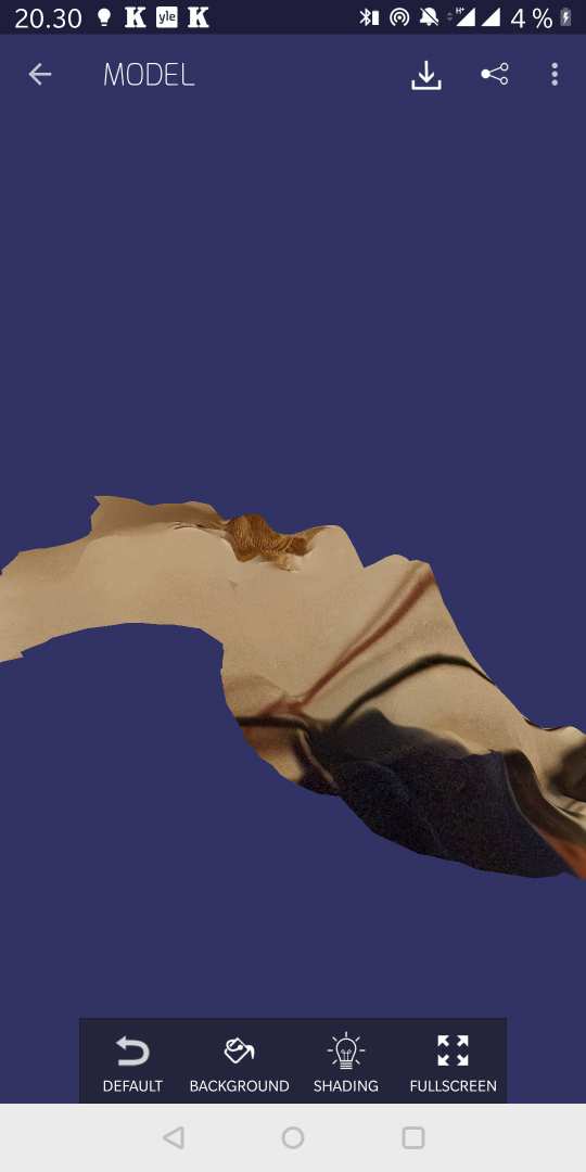
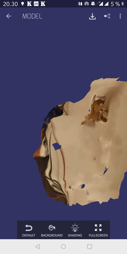
I wasnt' pretty surprised about low score in the reviews. Their "patent pending photogrammetry technology" didn't work well. I had decent lightning conditions and had same "plastic cat" to be scanned than with other applications, but this result was poor
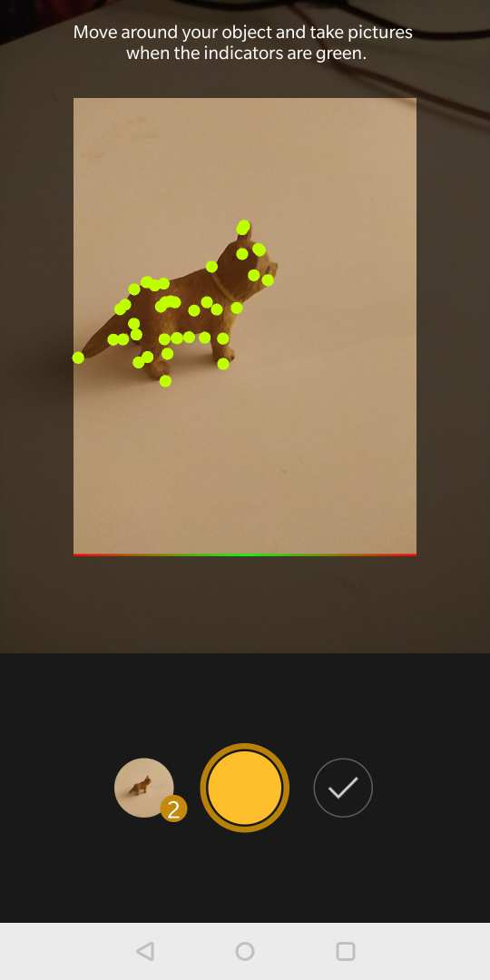
How to scan with Scann3D
Put object on the table
Choose "new model" from the main menu
Start scanning: you need to take approximately 20 pictures and be sure that in each pictures you see green dots on your model. application indicates correct shooting posture by changing colors of the dots between red (very bad) to green (very good)
When you have taken 20 photos, you can click continue (button next to yellow shooting button
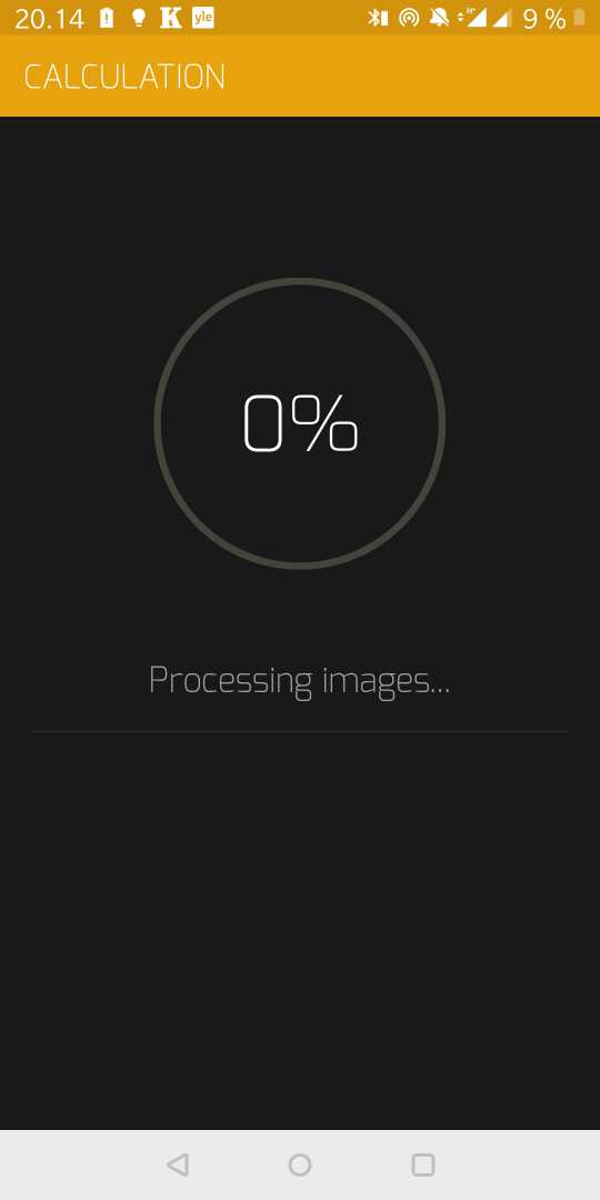
Device will start to calculate your model
When calculation is done, you can view your model
My 3D scan experience with Scann3D wasn't successful. Result is below.
Qlone
Qlone was better of these two applications, for two reasons: user interface was intuitive enough and it did really decent 3D scanning result. So, actually it did work and it did work pretty well. Below are two separate introductions what the application is and then I describe steps of using it:
"Qlone, the all-in-one tool for 3D scanning. We have made it easy and fast to 3D scan real objects, using your phone's camera, modify them in app and seamlessly export the result to many platforms, 3D file formats and 3D printers… all on your iPhone or iPad. A perfect tool for AR/VR (Augmented Reality) content creation, 3D Printing, STEM Education, eCommerce showcase and many other uses. (Google Appstore")
average of user reviews: four starts
3D scanning is something that most Android users – until the release of Google’s ARCore – still didn’t know about. And that’s understandable, since there is no easy way to do 3D scanning on your phone, unless you had one of those developer kits from the old Project Tango. With the recent release of ARCore, a lot more people are experiencing 3D through augmented reality (AR) elements. Maybe it’s time for people to start 3D scanning with their own phones – and that’s where the new Qlone app comes in. (https://androidcommunity.com/qlone-3d-scanning-app-now-available-for-android-20180308/)
How to use this Q-lone to scan and view scanned products:
You need to print raster mat which will be used to recognize position of the object you are scanning
When you have printed "Qlone mat" put object to be scanned on top of the mat
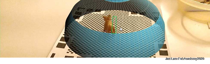
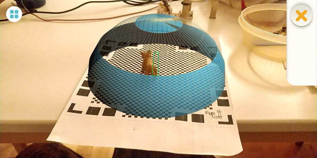
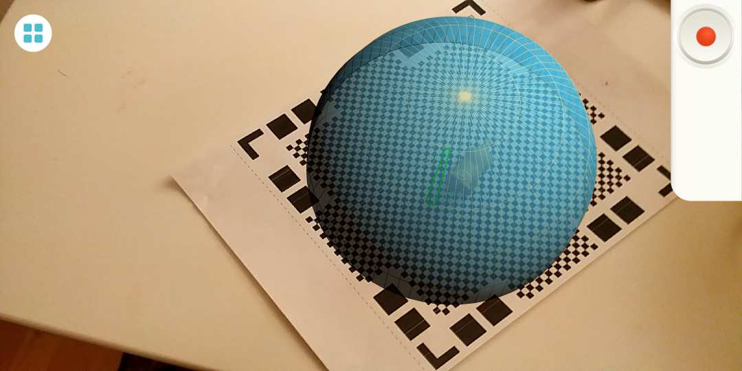
Turn on the application and start scanning, it will be started with calibration: you need to move your mobile phone so that all segments of the dome will disappear (see photos)
When calibration is done, you need to move phone again to remove segments of the similar dome (see photos)
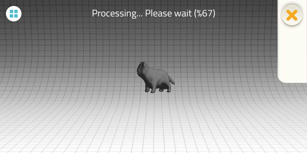
Next step is calculating process, I did choose minimum settings and quality of those is visible in the pictures
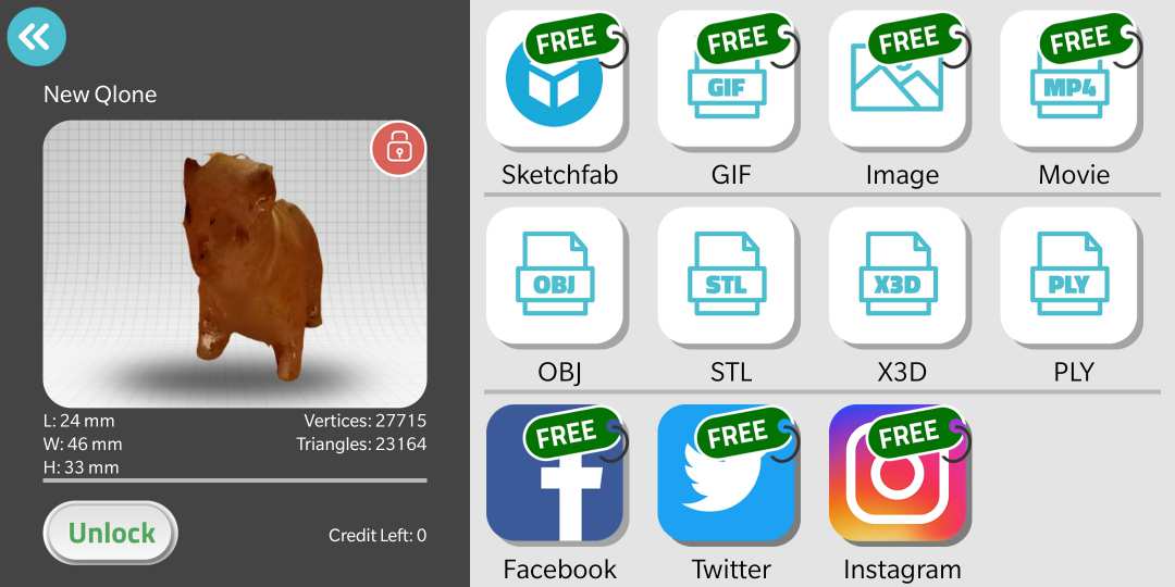
After your object is calculated, you can share it without paying e.g. to social media and some 3D object sharing services.
However, if you want .stl, .obj etc files, you need to unlock your model. Minimum payment was 10 euros - I did choose it
After unlocking the model, you can save e.g. stl model to google drive and print it later on
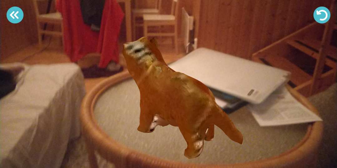
In the object viewer you can click "AR" button and place your model anywhere in your context. I put my cat onto sofa table. With the help of integrated ARcore I was able to look my model from different angles in that certain location
Preparing scanned object for 3D printing and experiments with 3D paint
I continued with .stl-file that I got from 3D scanning app "Qlone". I noticed in the preview (Windows 3D paint) that scanned plastic cat has some rough areas and spikes in the area of the head.
I opened .stl-file in Fusion360 and navigated into MESH section. I did use "smooth tool" for removing worst spikes and smoothing roughest spots in the cat.
After this very mild treatment object is ready for 3D-print (I would use mesh-mixer, but it's very difficult to run on my computer [run only as administrator in my windows 10 computer and my laptop is managed by the university])
Instead, I will continue with 3D object towards mixed reality which is also natural direction for me as teacher educator. For example, early childhood education students could scan toy and continue with scanned object to adventurous digital worlds in the context of mixed reality
Adding texture, eyes etc. to scanned cat and taste of the Mixed reality
Microsoft Paint 3D is modern version of the classical paint bitmap drawing program. I opened .stl-file that I had exported from the fusion 360 after smoothing treatment in that program
In the Paint3D I used brush tools to add texture to cat, but also to draw nose and mustache to cat. For eyes I did use "stickers" tool,I just picked up suitable eyes from the readymade collection.
Then I tested how to immerse my design into camera picture (mixed reality). This worked pretty well and cat attached very well to my body movements.
I was pretty happy with the furry cat - textured version of the 3D scanned cat. So, I tried to export that textured version as .stl. However, I encountered some issues when I tried to do that:
Microsoft 3D paint doesn't support exporting .stl files - instead you need to export file as .3mf and open it Microsoft 3D builder and save it there as .stl. Pretty complicated workflow.
When you open .3mf in Microsoft 3D builder and save it as .stl, textures etc. disappear. So, other format might be better for exporting object from 3D Paint
I found from the Internet tutorials, that when I save my 3D paint project as .glb and open it in 3D builder, I can further save it as .obj (waveform file. By doing so, all texture and color information moved along the object)
When object is saved by using Waveform file (OBJ) -format, materials (including refererences to textures) are stored in compation .MTL file.
I found that using this format, I can keep also texture together with geometry data. However, I will attach into files only .stl-files, because of the big filesize of OBJ and companion files.
EXTRA TRYOUT: 3D Scanning with holotuber application - Hologram streaming for everyone!
I wanted to try volumetric video capture & realtime AR visualization as a 3D capture method. I got this idea on LinkedIN months ago, when japanese engineer Takashi Yoshinaga shared his first volumetric captures and pretty soon after that shared also his method with code to interested testers
However, at that time I didn't have nor time or interest to experiment with his tools, of course I didn't have required camera either. Month ago Takashi added support in HoloTuber kit to Kinect v1 camera, which made possible to experiment with HoloTuber with our existing XboX360 Kinect camera.
required software:
To broadcast hologram, Holotuber processing app, Kinect SDK1.8, Processing 2.2.1, SimpleOpenNI1.96, OBS Studio and YouTube account are needed.
Holotuber is processing application
Holotuber application is processing project. Processing is an open-source graphical library and integrated development environment built for the electronic arts, new media art, and visual design communities with the purpose of teaching non-programmers the fundamentals of computer programming in a visual context.
Holotuber version used in my experiment can capture RGB and Depth image from Kinect V1 & xtion to generate RGB-D combined image.
Install the last stable version of Processing IDE, you can download it from this page:https://processing.org/download/
Beware: installation wiki suggest to add openni just from processing IDE (skectch/import library/openni), but that part of the guide didn't work
Beware2: Download link didn't work either.
So, let's google how to openni library can be downloaded :) It seems to be pretty old library and difficult to install. So far, this project is now paused (thursday)
one tutorial, but didn't work:https://www.toomanybees.com/storytime/simple-open-ni
This approach did work through google code
Download as file: * Download SimpleOpenNI * Copy the extracted folder in your Processing library folder * Windows: C:\Users\'your username'\Documents\Processing\libraries * Linux: ~/sketchbook/libraries * OSX: /Users/'your username'/Documents/Processing/libraries
In my case I was dependent of using old Kinect 360-sensor and support for that sensor is not good anymore. Only OSX version for required components was up-to-the-date. In order to proceed with this approach, I should buy more recent stereoscopic camera.
		  error:
			UnsatisfiedLinkError: Expecting an absolute path of the library: /lipasto/kotidir02$/jlaru/My Documents/Processing/libraries/SimpleOpenNI/library/win64/OpenNI2.dll A library relies on native code that's not available.
Or only works properly when the sketch is run as a 32-bit application.
Yep. Can't continue anymore with this XBOX Kinect 360 approach.